-


Harris 3100331 - 351-60Ar-580 Cylinder Flowmeter Argon/Carbon Dioxide Regulator Regulator
$108.07$144.62Unit price /Unavailable
Harris Model HSD 1/2 Single 7/8"-14 RH Inert Gas/Air Station Drop - 4300808
$224.68$244.63Unit price /Unavailable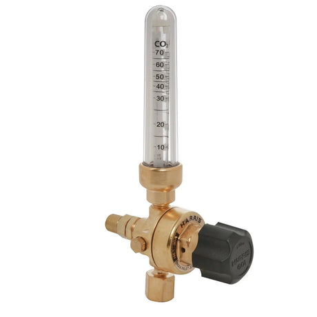
Harris 3100332 - 351-70Ar/CD 1/4 M Pipeline Flowmeter Argon/Carbon Dioxide Regulator
$112.16$153.35Unit price /Unavailable
Harris 3100330 - 351-60CD-320 Cylinder Flowmeter Argon/Carbon Dioxide Regulator Regulator
$108.07$144.62Unit price /Unavailable
Harris 3100334 - 351-70Ar/CD 5/8 M Pipeline Flowmeter Argon/Carbon Dioxide Regulator
$123.07$153.35Unit price /Unavailable
Harris Model HSD 1/2 Double 5/8"-14 RH Inert Gas Station Drop - 4300811
$310.03$337.83Unit price /Unavailable
Harris Model HSD 1/2 Single 7/8"-14 RH Oxygen Station Drop - 4300805
$224.49$244.63Unit price /Unavailable
Harris 5400614 - 55-2Ar/CD 70 5/8 in.-18 Compensated Flowmeter
$163.07$200.97Unit price /Unavailable
Harris 447-125-CR Station Single Stage Oxygen Regulator Right Hand- 4000555
$387.23Unit price /Unavailable
Harris Model HSD 1/2 Single 7/8"-14 LH Fuel Gas Station Drop - 4300806
$224.49$244.63Unit price /Unavailable
Harris 3100333 - 351-70Ar/CD 9/16 F Pipeline Flowmeter Argon/Carbon Dioxide Regulator
$127.07$153.35Unit price /Unavailable $163.07
$200.97Unit price /Unavailable
Harris 447NC-200-1/4" RH Pipeline Single Stage Oxygen Regulator - 4000586
$330.28$384.31Unit price /Unavailable
Harris 5400610 - 55-2Ar/CD 70 1/4 in. NPT (M) Compensated Flowmeter
$163.07$200.97Unit price /Unavailable
Harris 447NC-200-1/4" RH F Pipeline Single Stage Air/Inert Gas Regulator - 4000590
$330.28$384.31Unit price /Unavailable
Harris Model HSD 1/2 Double 7/8"-14 RH Oxygen Station Drop - 4300809
$332.35$337.83Unit price /Unavailable


